Three-element boiler drum level control using the SC100/200 series
Multi-Function PID Controllers
Application Field: Boilers for power generation plants and process plants
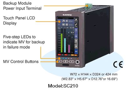
Product: SC210
A drum is a cylindrical reservoir of boiled water/steam, usually lying on its side and located near the top of a boiler.*1 It is used to separate steam for turning a steam turbine thus generate electricity.
Maintaining correct water level in the drum is critical for safe and efficient boiler operation. Too high a water level causes flooding and interfering with the process of separating moisture from steam within the drum. Too low a level results in low efficiency in the water/steam conversion and even in uncovering boiler tubes and damaging them. These requirements typically result in a narrow range in which the level must be maintained.
Steam flow and feedwater flow are two elements that affect the drum level. The addition of them to the drum level element provides tight water level control in the drum and this control strategy is called ‘three-element control.’ *2
*1. Drum boilers are used to generate high pressure steam, typically installed in relatively small power plants such as private power generation plant in a factory. Once-through boilers typically used in large-scale power plants do not have drums.
*2. Drum level control is also called ‘feedwater control,’ as its purpose with a drum boiler is to maintain a constant water level in the drum.
This article introduces an application example of the Multi-function PID Controller, model SC210 used to provide an effective control of drum level.
A basic objective of the drum level control is to manipulate feedwater flow in response to water level feedback in order to maintain a constant level. The water flow is manipulated typically by changing rotation speed of a feedwater pump or by opening/closing a control valve.
The feedback control explained above is acceptable if the boiler load (steam demand) is steady. However, a sudden change in the load would cause a transient disturbance called ‘reverse response of the drum level’*3 which is disruptive in its stability. In order to provide the tight control during both steady and transient conditions, the steam output flow, cause of the disturbance, is measured in advance of any change of the level, and is used to directly manipulate the feedwater. This is called ‘two-element control.’
Furthermore, the feedwater flow control loop added in cascade from the drum level control loop suppresses effects of the feedwater pressure variation and improves the controllability. The addition of these three elements, (1) drum level, (2) steam flow and (3) feedwater flow, enables the Controller to predict the amount of water added to the drum in spite of the disturbances to maintain the drum level.
Figure 1 shows an example of the SC210 function block combinations for the three-element boiler drum control. The PID control block output (MV) of the drum level control loop (LIC) is supplied as the setpoint (SP) of the second PID control block for the feedwater flow control loop (FIC) in cascade. The LIC output (MV) is added with the steam flow to compensate its variations (feedforward control).
Figure 1. Control loop configuration example
with the three-element drum level control.
All four models of the SC100/200 series controller can provide extensive software function blocks of addition/subtraction and leag/lag computation in addition to the PID control to realize a sophisticated control such as the three-element drum level control.
The model SC210, however, is especially suitable for use in a critical control loop such as for boilers thanks to its backup and manual loading functions. It has also Modbus/TCP communication capability to realize remote monitoring/control of the boilers from a SCADA system.
*3. Reverse response of the drum level drum.
When the pressure in the drum drops by a sudden increase of load (steam output flow), bubbles existing in the generating tubes expand and displace water in the tube to the drum, to create a misrepresentation of the true water level in the drum. The effect is reversed when the load decreases. Likewise, when the feedwater is added, the water level temporarily decreases due to the contraction of cooled bubbles. These phenomena are called ‘reverse response of the drum level.’
The Controller temporarily increases feedwater to offset the effect when the load surges.
Figure 2. Drum level fluctuation example
(reverse response).